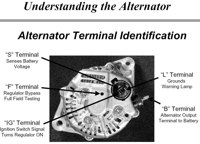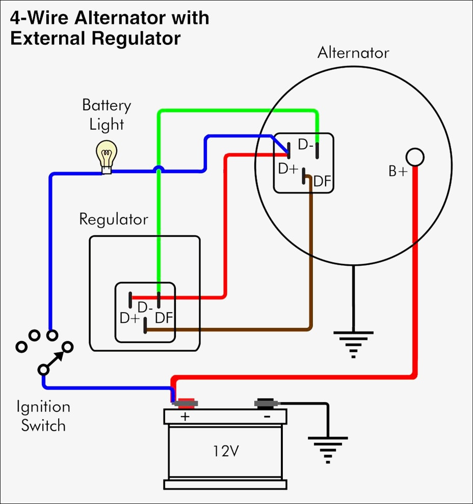

It's going to be a while before I get my Nova into condition to actually test the alternator and this wiring but I'm fairlyĬonfident this is what will work. Had wired the harness correctly but just couldn't figure out why there was no diode or resistor in what I was trying to do. When I was doing all the tests I never paid attention to the continuity readings just the beep. I have a continuity beeper in my Simpson Multi-meter and There was the resistor! I did the measurement again and got a reading of 9.5 ohms.Īll the other wiring in the harness read around 0.5 ohms. Notation was not on the diagram that I purchased which was the " 1965 Chevy II Nova WIRING DIAGRAMS FOR SNS and noticed that the wire from the fuse panel to the ignition switch had a notation that said "resistance wire" andĪn arrow pointing to the brown/white wire! The brown wire changed from Brown to Brown/white at the fuse panel.
3 wire alternator wiring diagram full#
I printed out a '65 full diagram from our page here on Here is where I finally figured out what the heck was going on.

Traced that brown wire through the fuse panel assembly and over to the ignition switch. I went back, starting with the brown wire on the white connector for the alternator and The whole thing about a diode or resistor was what was totally confusing me as it was obvious there was no diode or I ran through the connections and he assured me that my harness was built for the 10SIĪlternator and no bulbs which would be the SS and would work. I explained what I was doing about drawing a new diagram of my car that has no idiot lights and I confirmed that my alternator was in fact a 3-wire. Ok, I’m wanting your approval before I start drawing my front harness diagram. I know this is a lot of hoopla about almost nothing but I want to make sure my diagram drawing is correct when I get through with it. It doesn’t appear there is a diode inside the wrap as the connection from the small red wire to the large red wire reads zero (0) resistance. This splice is wrapped inside the harness. The small red wire loops inside the harness and go to the big red connector for the BAT. Now, looking at the new harness there is a brown wire, shown in the photo, that is going from the 10SI alternator and I followed it through the harness to the dash harness and it does go to the ACC on the IGN. I was thinking that was for switched power. Looking at the diagram for the old alternator, there is a brown wire that goes from the regulator and over to the ACC on the IGN switch. When I ordered my front wiring harness from AAW I told them that I would be using the 10SI and it appears it is wired like what I have in the photo.
3 wire alternator wiring diagram upgrade#
I’ve bookmarked your link for future reference just in case I do need to upgrade later. To answer your comment Firebird, I've already bought this alternator and I don’t think I’ll ever need any more power than what the 10SI can provide.


 0 kommentar(er)
